Disclaimer: Due to unforeseen difficulties, we have had to take down the images on this notes page. They will be replaced shortly. We apologise for the inconvenience, but hope that the new images will provide you with an even better learning experience.
- Draw and interpret circuit diagrams containing sources, switches, resistors (fixed and variable), lamps, ammeters voltmeters, and fuses.
A circuit is made up of many components. Let’s meet some of them:
Source/battery: the device that stores energy and provides the e.m.f. required for the circuit to function. It’s symbol in a circuit will look like this:
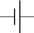
(The short line indicates the negative terminal and the long line indicates the positive terminal. This is a cell since there are only two lines. But when many alternating short and long lines are drawn, it is called a battery!)
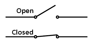
Switch: a switch, when closed, will allow electricity to flow through the entire circuit. When opened, it will break the circuit. Below is the symbol for an open switch and closed switch.
Resistor: a resistor is a device that limits or resists the current flow. A resistor will increase resistance of the current. It can be fixed (a fixed amount of resistance will be provided) or variable (the resistance can be changed to suit our needs). The symbols for each are:


Both of the above can be used as symbols for fixed resistors.


Both of the above can be used a symbols for variable resistors
Lamp: in a simple circuit that has a lamp which will light up when electricity flows through the circuit, it’s symbol will look like any of these two:


Ammeter: the device that measures the amount of current flowing in a circuit. It’s symbol is:

Voltmeter: the device that measures the amount of p.d. across a device in a circuit. It’s symbol is:

Fuse: the fuse is a length of wire that melts when a high current flows through it, breaking the circuit and helping prevent any electrical damage or injury. It’s symbol is this:

Now that you know some basic components of a circuit, let’s look at a simple circuit.
In this circuit, there is a battery; a switch that is currently open, indicating that the there is no current flowing; several fixed resistors; an ammeter that will measure the current; and a voltmeter that will measure the p.d. across the topmost resistor since it is positioned directly parallel to that resistor (voltmeters should always be positioned directly parallel to the component they’re measuring)
- Draw and interpret circuit diagrams containing magnetising coils, transformers, bells and relays.
Magnetising coil/ electromagnet: used in a variety of circuits to turn it on and off. It can be drawn in either of these ways:


Transformer: used to step-up or step-down the voltage of current being delivered.

(It is also drawn as a coil (like that of the electromagnet’s symbol). The number of coils on each side can be different depending on whether it is a step-down or step-up transformer. More on that here.)
Bell: many circuits may contain electric bells and their symbol is:

Relay: A relay is an electrically operated switch. Many relays use an electromagnet to mechanically operate a switch. It’s symbol looks like this:

(Notice how the relay symbol is a combination of an electromagnet and a switch, which makes a relay. The electromagnet part is sometimes simply drawn as a rectangle. Check past papers to see how it is drawn in them.)
Notes submitted by Lintha
Click here to go to the next topic.
Click here to go back to the previous topic.
Click here go back to the Science menu.
